Automotive Lighting Solutions
Turn-Key Solution Partner for Automotive Lighting Projects
Optonom assists you to realize your project related to Automotive Lighting. We can produce injection molded aspheric lenses and free-form lenses and Light guides for Automotive Lighting Applications. We provide turn-key solutions like "OPTICAL ENGINEERING + PROTOTYPING + PRECISE OPTICAL MOLDING + PLASTIC INJECTION PRODUCTION" with related international ECE standards.
---------- PHOTOMETRIC BASIS ----------
LIGHT INTENSITY
The intensity is the luminous energy from a lighting
source in a specific direction:
- Symbol: I
- Unit: Candela (cd)
Light intensity varies depending on which direction
the light source is being viewed from.
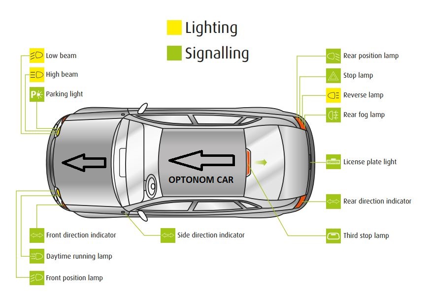
Some examples of Candela intensity on automotive
lighting systems:
- A candle: 1 cd (reference)
- Parking lights: 2cd
- Position lights: 4 cd
- Direction lights: 50 cd
- Stop lights: 60 cd
- Reversing lights: 80 cd
- Fog lights: 150 cd
- Daytime Running Lights: 500 cd
- Low/High beams >1000 cd
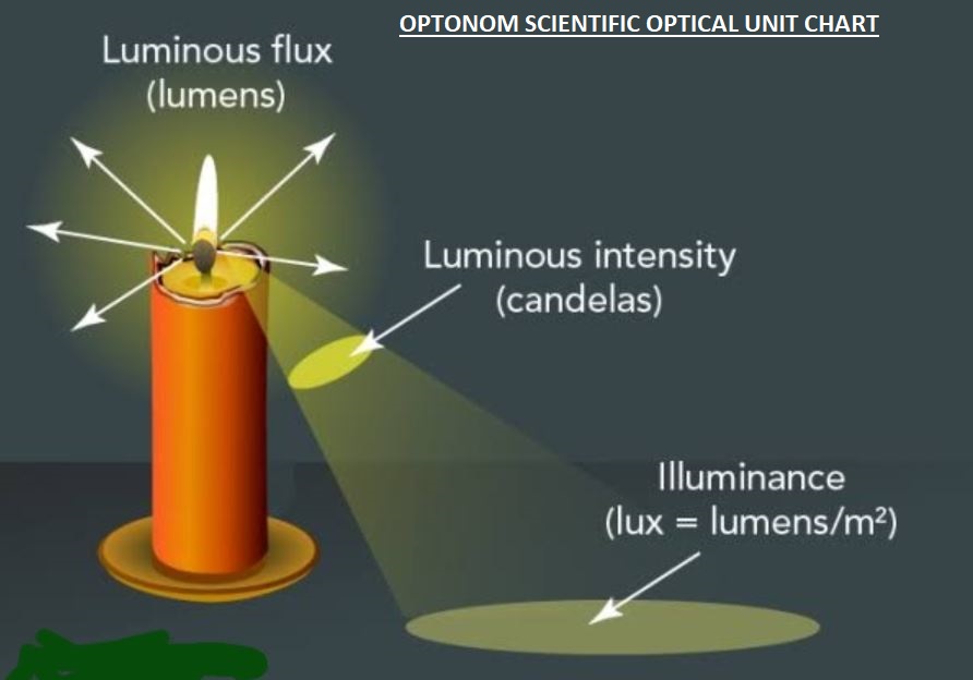
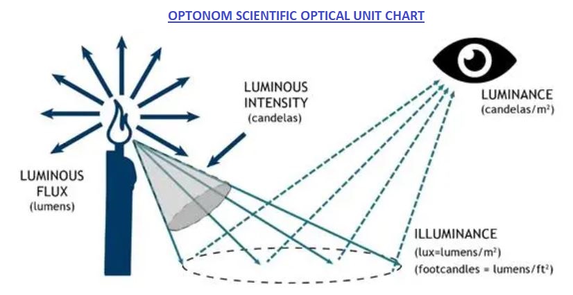
LUMINOUS FLUX
The luminous flux is the complete light output
radiated from a light source.
- Symbol: Ø
- Unit: Lumen (lm)
The Lumen unit is defined based on the human
eye sensitivity curve
ILLUMINANCE
The luminous flux from a light source (lumens)
falling on a unit of surface (m2) is called illuminance.
- Symbol: E
- Unit: Lumen/m2 also called Lux
The illumination level does not make allowance
for the amount of light reflected off the surface.
The reflected light is called the luminance; this
depends on the nature of the surface, including its
colour.
LUMINANCE
The luminance measures the reflected light from a
surface to a given direction; the surface can itself be
light-emitting, transmitting or reflecting light from
another source.
The luminance is the perceived brightness, it is used
to categorise:
- Light sources (eg. lamps).
- Lighting systems (eg. headlights).
- Any surface that is bright (eg. road signs).
The luminance is related to a luminous intensity
emitted per unit of area from a surface in a specific
direction.
- Symbol: L
- Unit: Candela per m2
ECE Regulations for Lighting
European Commission regulations for lighting system
are classified as follows:
ECE R37 => LIGHT SOURCES - FILAMENT LAMPS
ECE R99 => LIGHT SOURCES - HID LAMPS
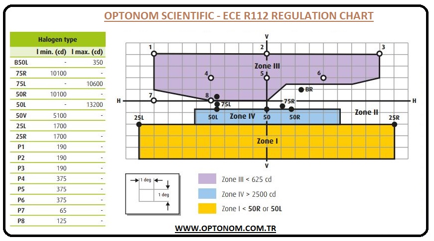
ECE R112 => LOW AND HIGH BEAMS - FOR HALOGEN LAMPS AND
LED SOURCES
ECE R98 => LOW AND HIGH BEAMS - HID LAMP SOURCES
ECE R19 => BEAMS - FRONT FOG LAMPS
ECE R87 => DAYTIME RUNNING LAMPS
ECE R48 => SETUP ON THE CAR
ECE R123 => AFS BEAMS - HALOGEN, XENON AND LED LIGHT
SOURCES
Headlamp Lighting System
A good front lighting function provides maximum
visibility with minimum inconvenience for other
road users.
Headlight beams are standard patterns that set
the light projection levels and limits on the road.
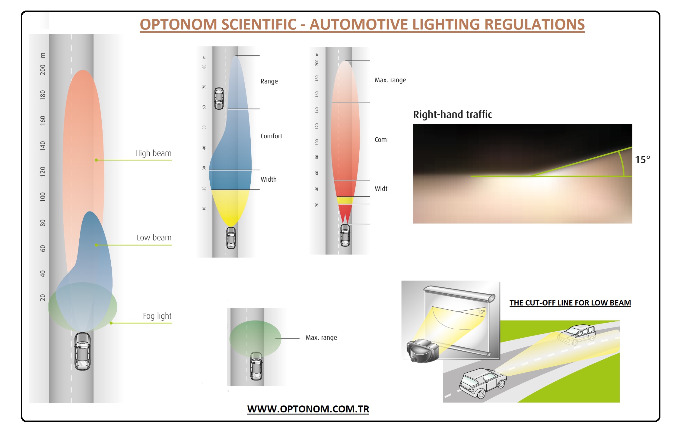
Several beams are defined:
- Low beam also called passing beam or dipped
beam.
- High beam also called main-beam or full-beam.
- Fog beam.
Beam types
Beams can be defined according to their shape and
performance:
- The “Width” area: where illuminance covers the
whole road width in the driver’s near field of view.
- The “Comfort” area: which corresponds to the
driver main vision zone.
- The “Range” area: where the maximum
illuminance level occurs far on up to the road.
The cut-off Line
Depending on their type, projectors must include a
system to produce a cut-off line.
The cut-off line defines a limit where light should
not be projected, low beams and fog beams must
comply with this but no legislative cut-off point is
required for the high beams.
Low beam
- Must be orientated downwards.
- Must respect a cut-off line to avoid glazing the
oncoming driver.
Daytime Running Light (DRL)
Daytime Running Lights belong to the signalling
product family. DRLs are a perfect example of a
high luminance application, they produce a huge
intensity of light in a compact reflector.
The ECE R87 regulation specifies an apparent surface
between 25 cm² and 200 cm², and an intensity level
between 400 and 1200 cd.
The apparent surface and the intensity permit to
calculate and see how huge can be the maximum
luminance level on Daytime Running Lamps
(480000 cd/m2).
As for lighting, the signalling devices have to comply
with photometric specifications.
European Commission standard (ECE R.) set
photometric limits and all measurement conditions.
Minimum and maximum intensity values are
defined in various directions of measurement, the
minimum intensities are defined as a percentage
of the minimum required in the axis for each lamp
(100% in the direction H = 0° and V = 0°)
For detailed technical document click here

.png)
